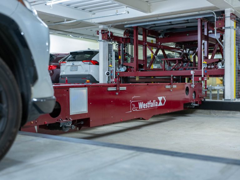
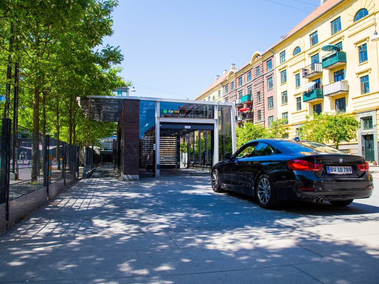
Siemens recently published a comprehensive case study highlighting our successful partnership on Philadelphia's prestigious 500 Walnut automated parking project, showcasing seven years of proven reliability and our vertically integrated approach.
Automated Warehouse Solutions
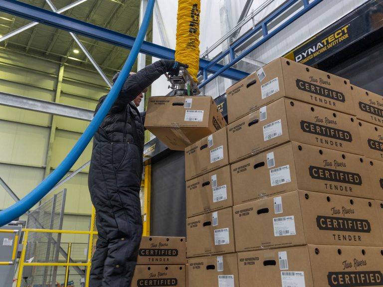
Industry: Beverage
Partnerships In Automation
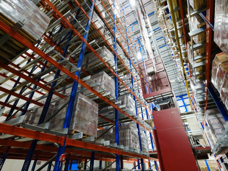
Manhattan Beer & Beverage Distributors has implemented a new pallet AS/RS system that automates and expands their reserve storage capabilities while improving material flow through a major site rebuild. This strategic automation investment boosts network capacity, strengthens regional customer service, and advances their sustainability goals.
Innovative automated parking garage at 4211 Chestnut Street, offering student housing with contemporary amenities and short-term stay options in an elevated urban setting.
Automated Warehouse Solutions
Partnerships In Automation
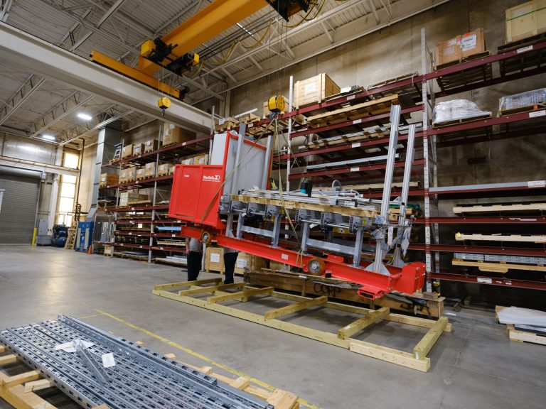
Empirical Foods resolved significant challenges in their automated storage system at the TRD warehouse, enhancing operational efficiency and reliability.
Learn how to solve 9 common warehouse challenges, from inaccurate inventory to high labor costs, using automation and smart technology to improve efficiency.